
|


|
###### NEW: 6/2/01: ####### I have found that the coil is one of the most important factors of the ion tweeter's construction. It should be wound with low-resistance magnet wire, perhaps 14ga to 16ga copper wire. This will minimize the DC resistance, Rdc. The coil operates best when it has NO ways of losing its stored engery. The things that cause it to be inefficient are Rdc and the parallel resistance, Rac. Ideally, Rdc would be 0 ohms, and Rac would be infinite. What's left over is the Reactive components, Xac. The coil operates in self-resonance, where |Xac| is maximized. I use the absolute value "| |" because in self resonance, it is just at the point where the maximum inducance is being cancelled by the maximum capacitance of the windings. It is at this resonant frequency where the Rac goes way up (370kohms in my one coil). In effect, the optimum coil is the one that has the highest Q-factor. The Q-factor relates the voltage produced as a result of the oscillation to the bandwidth of frequencies over which the oscillation occurs, so a high Q coil has a very narrow bandwidth, which requires the feedback-driven oscillator circuit to keep it in optimum oscillation. It is important to wind the coil on a non-conductive core with about 2 thread's lengths of spead between the windings. I will be experimenting further with how to optimize these characteristics. See graphs. ###########
First, in order to justify this project, I'd like to introduce myself as an "audiophile". My defintion of "audiophile" is some person, preferably an electronics hobbiest, who goes to any extreme to get the sound he's after. These tweeters require a ridiculous amount of power (around 150 Watts, whether at 100dB or idle!), generate a tremendous amount of heat (do the words "Plasma Flame" help illustrate this?), cost a lot (~$300/pair from all new parts), generate ozone, and may cause interference. None the less, they sound fantastic, unlike anything I have ever heard, they radiate very clear, open sound from a true point source (spherically, 360°), with perfect transient response, no Doppler distortion, and they use the same principle which nature uses to create sound from electricity (lightning & thunder).
So, without futher ado, let the hobbies begin!
I found the idea for this crazy project at Ulrich Haumann's Vintage Audio
Website http://members.aol.com/uhaumann/index.htm. He has a "gallary" of
Plasma Tweeters on display here, and gives schematics where possible. This project
comes from his DIY Plasma Tweeter,
where he supplies schematics, instructions and
tips for building these. You will notice that mine look quite different from his -
I just decided to build them different, that's all (well, I am using a horizontal
sweep tube in a vertical position, is this orthodox? I didn't grow up with
tubes, you know!). Same circuit (mostly), different layout. Same fantastic sound.
Petter, from Norway, emailed an interesting letter about some really neat plasma speaker using helium gas and 5 tubes.
I am willing to construct these tweeters on request, time permitting. Email me for details, but I have become increasingly busy recently, so I may be able to do no more than give pointers.
 |
DIY Plasma Tweeter |
 |
Parts List |
||
Fun Stuff |
||
My Schematics |
Good things:
(1) Mouser Electronics sells a 100µH, 1-amp choke that people have had trouble locating. The part number is: "434-11-101M" and they cost just $0.76 a piece. These ones are made by Xicon and work perfectly on the tweeter.
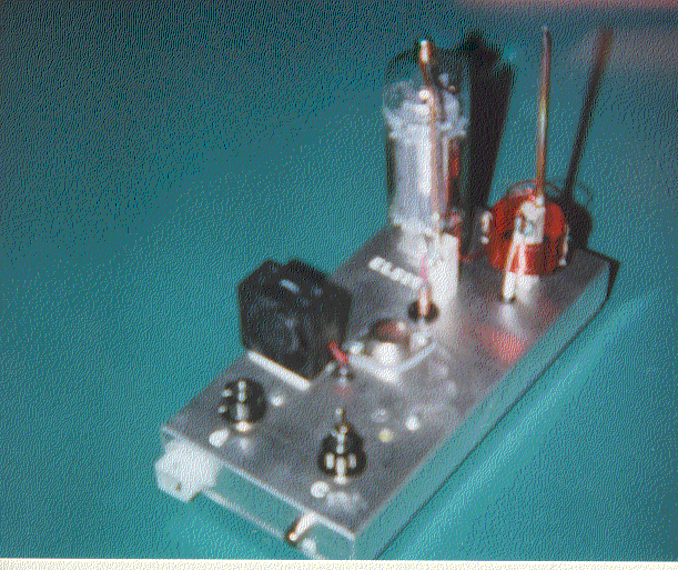
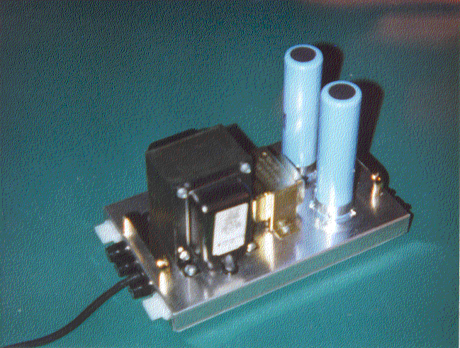
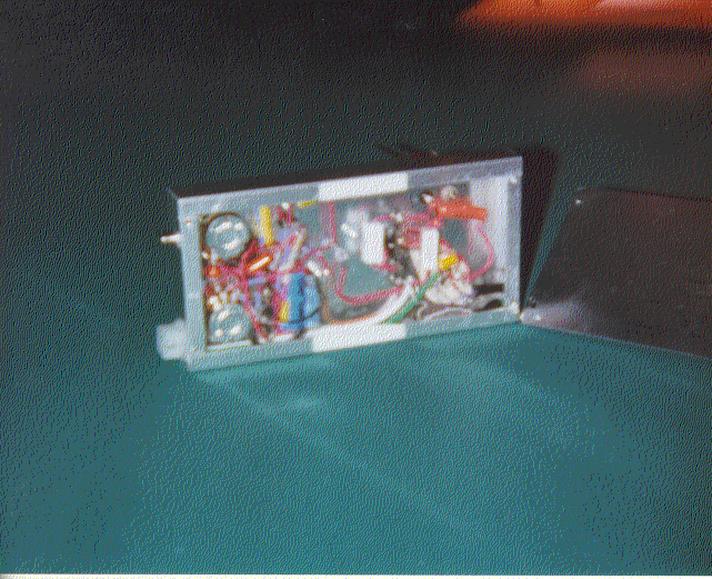
(2) I put all the pre-amplification electronics inside my 8x4x1" aluminum chassis and left only the tube, RF-choke and tesla coil outside. This helps separate any noise the tube and coil might generate. I constructed one power supply completely separate from the tweeters to isolate any transformer noise.
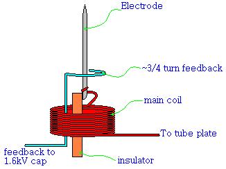
(3) The ceramic core for the tesla coil was impossible for me to find. I liked the idea of having the coil "float" in mid air, connected only by its 18-gauge magnet-wire leads. I used Duco Model cement on the coil thinking that it should work fine. Strangely, while the coil is hooked up the high-powered oscillator on the one lead and the other lead goes into the air, the coil heats up hot enough to boil the model cement!! The cement works for a little while and then becomes extremely brittle from the heat. After many other different strategies, I ended up winding the coil on a cardboard tube with four slits cut into it, through which I threaded the magnet-wire loops together with medium-duty sewing thread. I further soaked the thread in super-glue (the cyanoacrylate type). These coils have held up wonderfully and show no signs of wear. The only potential problem is that there is a small gap between the wire loops from the thread, which may reduce the strength of the coil a little bit (or maybe not).
I did try soaking one coil in red lock-tite, but when I tested it, it didn't work. I first thought it was because the lock-tite was conductive, but I later found that I had a bad tube! I still think the lock-tite will work very well, but I vaguely recall that one way of removing lock-tite is to heat it, so that might also be a problem. Cast your own concrete rods, you can't go wrong there. Maybe wind the coil on a shot-glass?
The other question was this 3/4-turn feedback loop. What is it? I don't know, but I do know that the tweeter works when the loop is on the output side of the tesla coil, and doesn't work when it's on the cold side. I don't know if it picks up voltage inductively, capactively, both, by air-resistance, magnetically, by train, plane or automobile. But as long as it works, I'm happy.
(4) On the power supply, I used one switch to turn on the tube filaments and one to turn on the 300 & 600-volt outputs. The advantage of this is that you can turn on the filaments to warm up the tube, and flip the high voltage switch after a few minutes, and, "pop," the tweeters light themselves every time!!
(5) I used 3/16" copper tubing for the electrodes, which I pinched and snipped at the end for a nice sharp, ion-emitting point. This seems to work pretty well, but if you can find solid copper, that's even better. See also mistake #4 below...
(6) I used heavy insulation, 14-gauge, 4-conductor wire for the filament and main power for the tweeters. These cables are 12-feet long and have molex connectors on the ends for easy removal. See also mistake #5 below...
(7) I installed LEDs on the power supply and tweeters to indicate the presence of the filament voltage, the high voltage and, on the power supply, blown fuses. I haven't yet connected the red LEDs on the tweeters. Can't think of what to use them for yet.
Back up to the Menu(1) I bought an autoformer (where the primary is a part of the secondary), thinking, "hey, I'm saving money, saving space, saving weight" and not thinking "it's not isolated!" Now my power supply and tweeter chassies are at a 300-volt potential when the high voltage is on! D'oh! Not only that, but I needed to build a ground isolator (a 1µF, 600-volt capacitor) for the input on the tweeters to match the true ground output of my preamp. I have been shocked once in a while, but quickly learned to watch my p's and q's when the power is on (and even when it's off, since the 400µF, 400-volt caps can pounce a LOT of joules for the ounce!). Just spend the extra $10 for an isolated transformer!
(2) I also decided to be fancy and put small, on-board fans right on the chassis of each tweeter to cool the infrared emitting tube. This looks pretty neat-o, but the controller circuit in the fans spikes the power and puts noise in the tweeters. Strike two!
(3) This mistake is minor, but something to think about. A plasma tweeter has a very strong electric flame burning on the end of the electrode. This gives off ozone, which attacks rubber. I, wanting make them look a little more professional, used rubber grommets on the chassis. Luckily, the ozone emitted by the tweeters is minimal and very hot, so it rises away from the chassis. Use rubber anyway.
(4) Since the copper-tube electrode was pinched flat and snipped, I feared that the minute slit in the snipped edge would change the sound, so I put solder over it. After a few minutes of having the tweeters on, I noticed that the solder was vaporizing from the intense heat! That made a neat silver coating appear on the electrode, but I didn't like the idea of having solder vapor in the air! Use high-silver solder if you think sealing a slit might be necessary.
(5) I also constructed 12-foot RCA audio cables for the signal going to the tweeters, but made them using 6-conductor, unshielded solid telephone cable, thinking that the 6-conductors would be randomly intermingled and help block out noise. Since they are not shielded, they seem to pick up noise. I might be wrong about this, it's hard to tell. I think the noise problem may actually be more related to an impedance mismatch between the high output impedance tube and the high input impedance tweeter. This makes it easy for the wires to pick up noise.
Back up to the Menu(1) The highest sound output I got from my tweeters using my FM tuner's low-level outputs was about 76dB, with the gain all the way up (makes for an orange tube!)- not very loud. I connected and old, modified Fisher Vacuum Tube Phono Preamp Kit between the tweeter and source and it pumped out 98dB at only half-gain!! At 100dB (still half-gain), I heard distortion, but that was due to the limits of my Fisher Preamp, not the limits of the tweeter. I was putting +/-1.5v into the tweeter before the preamp clipped. I'm not sure what the input limit is on the tweeter's preamp is, so I would say build an op-amp preamp capable of +/-6v and you should be set for even more dB!
11/12/99: I built an op-amp preamplifier circuit which put out about +/-6v. I had it rigged up to a function generator for testing. The tweeter got so loud it started intermodulation distortion in my ears (sounds like wind). I think it may have been around 110dB, but I didn't test it. I really don't know what the upper limit of these tweeters is, but I was really impressed!
1/26/01: Tested sound output of Second Plasma Tweeters, which use the same final stage as this first pair. Measured 108dB at 2" from the flame. Probably could go higher. At 1 meter, it measured 86dB, but it sure sounded louder than that. I guess the sound meter mostly picked up the sound coming directly from the tweeter. This sound reflects off of everything and makes it seem like the sound is coming from everywhere with equal frequency content. I'm sure the sound at 1 meter would be much higher if I used a sound-focusing horn, but I really like the 360 sound dispersion, especially with two tweeters in stereo.
(2) Try putting an isolated screwdriver near the electrode while sound is coming out of it. You can literally pull the sound to whatever point you want on the electrode!
(3) Build a delay circuit in the power supply which closes a relay to turn on the high voltage 2 minutes after the filaments turn on, if the fuses aren't blown. This way, you get an automatic start every time (as long as your gain is set >~35%). You could also build a circuit which detects blown filaments, or the power used for the output, etc.
(4) At least for the testing phase, you will want some way of turning the high voltage on and off at the tweeters so you don't have to turn your power supply off and on for trouble shooting. This comes in handy when you want your tweeter to light, but not have to wait for the power supply capactors to drain.
(5) You may also want some way of keeping you capacitors trickle charged so they don't make your lights flicker when you turn the power supply on. Don't forget to cut off the outputs too, or you will drain the caps.
(6) You can literally cut a neon bulb in half by "drilling" a hole in the glass with the plasma and slowly rotating it. The neon glows purple instead of orange, and the glass glows white when the plasma starts drilling into it.
(7) Hold a fluorescent lamp near the electrode to start the lamp. You can scope out the strength of the electric fields by simply moving the lamp around the tweeters.
Back up to the Menu
 |
 |
 |
 |
 |
 |
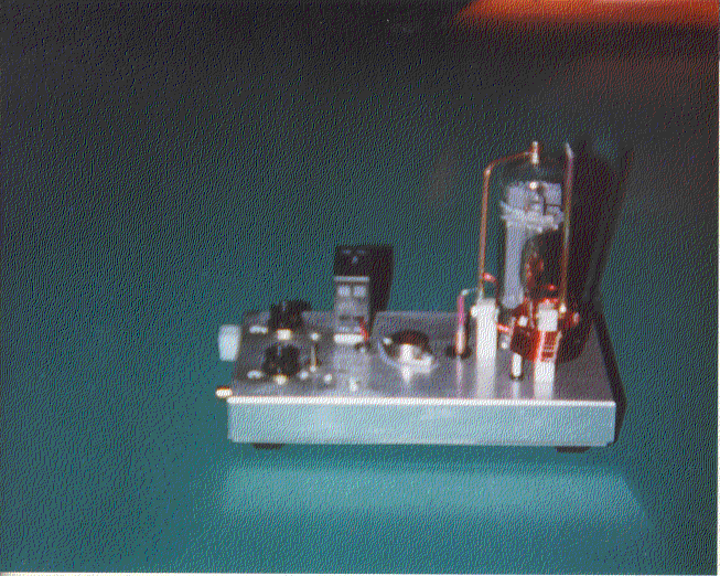
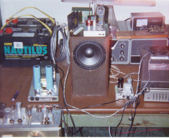
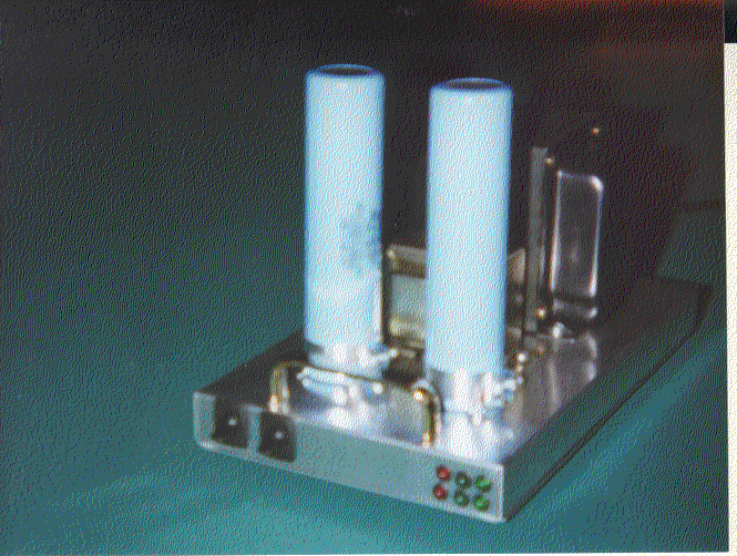
The pictures aren't that great, but you get the idea.
Click on for larger picture.
Back up to the Menu
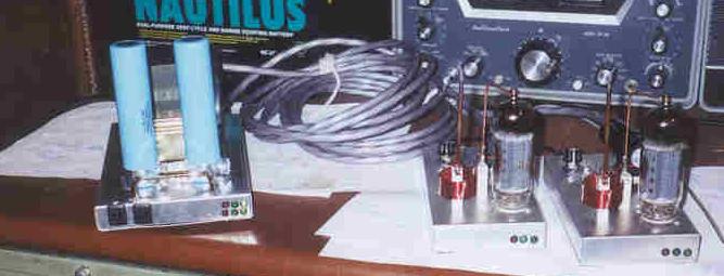
This is a picture of the complete set.
"No longer do I call you servants, for a servant does not know what his master is doing; but I have called you friends, for all things I heard from My Father I have made known to you. You did not choose Me, but I chose you and appointed you that you should go and bear fruit, and that your fruit should remain..." -- John 15:15-16 (NKJV)