Index
IntroductionHow it works
Instructions for building
Parts
Resonanz coil
Working Instructions
The End
Update 8/2001
The new Modulation Part is finished. It is now a complete Tube design. The modulator is now more efficient. The old transistor modulator, you find the schematic in the builders links, was not the best. With the new modulator the tweeter can play louder ! You can connect the modulator direct to the Loudspeaker output of your amp. The modulator need no power from your amp because it is voltage driven. Only 2Vss is needed for full output.Schematics Pictures
- Front View (24KB)
- Rear View (30KB)
- Open Top View (68KB)
- Open side view right (57KB)
- Open detail (55KB)
The first time I heard a Plasma-Tweeter was at a Hi-Fi show in the 80´s. I was really impressed by the sound. I had also the chance to talk to the development engineer Dr. Siegfried Klein but he told me nothing about the functional details. Few years later a defect IONOFANE 601 Plasma-Tweeter was brought to me for repairing. With this sample I was able to study the details and built my own prototype.
back to Top
It is really simple. It is a modulated RF power amp with a controlled ionic discharge.
By modulating the oscillator with the audio signal the flame size changed and so the air pressure changed also . You hear the sound directly through the air without modulating a diaphragm.
So there are no moving parts, no distortion and none of the problems other tweeters have. The signal is quite low in level ( I measured 82 dB with my prototypes ) but it is the cleanest sound I ever heard. I use no horns to increase the sound pressure so you dont have to sit in axis of the tweeter, the sound is everywere in the air.
You need a lot of RF power to get a ionic flame so I use a tube (valve). I choose a EL519 you can also use a PL519, the PL has only a different heater voltage ( 40 Volt / 300 mA ). The RF power is easily modulatet on G2 of the valve. I use a transistor, it was the simplest method for the prototype. ( Aug. 2001 )The tube modulator is now finished.
 |
The loudspeaker input go´s through a passive 6dB crossover to the first
tube. With the 47K resistor and the 1n cap the crossover frequency is
at 3,4Khz. I messure the frequency response at a distance of 1 meter with passive crossover at 5Khz. The ripple you see in the curve is from the room because I measure in 1m distance. |
 |
For the picture the gain control was put to maximum to get a large flame. In normal operation the flame is appr. 5mm high. |
Click on the thumbs for large pictures.
Please note that a careful building in a steel or aluminium chassis is strongly recommended. The part with the power tube and teslacoil is covered with perforated steel. The holes are 3 to 6mm. There is a lot of heat coming out.
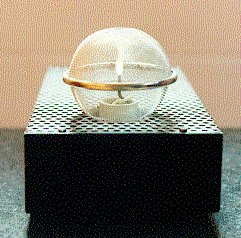
I have divided the tweeter in two sections. One section for the tube and teslacoil and one section for the rest. If I had a second chance I prefer 3 sections to separate power and amplification because it was not so easy to get the noise from the powersupply away from the amplifier. The sections are separated with a aluminium plate. I use this plate also as heatsink for the transistors. In the perforated cover I cut a 50mm hole over the place were the teslacoil is positioned. The electrode of the teslacoil comes out of this hole. Over this hole I put a ball made of 2 teasieves, which I soldered together. In that ball you have to drill a hole ( 6mm dia.) in the height of the electrode. See the ball picture how this looks like.
That's the mechanical part. The potis and connectors are placed on the rear. See rearpicture. The wireing is like in old tubeamps "free air". Be careful with the grounding otherwise the speaker gets hum !
back to top
I tried to use standard parts. The transformer is a 120VA type, secondary voltage 230V. The heater voltage depends on the tube you use. For the EL519 you need 6.3V, for the PL519 you need 40V. All resistors are 1Watt metall types. The 18 Ohm Anode resistor is a 5Watt wire type. The RF coil ( DR in the schematic )is a Siemens 100uH / 1Ampere type. I tried other RF coils but they did not work properly. ( If someone has realy problems to get this type of coil, I have some spares but this is not my business)
back to top
 |
This is the main part of the speaker. You have to build it by
yourself. Don't worry it is easy. You can even do it with a glass of
beer or wine on the building desk. What you need is a ceramic body with 35mm diameter, aprox. 70 mm long ( length is not critical). I get my ones on a ham radio flea market. ( I spent 5$ ). The wire I use is 0.9mm paint isolated copper wire. It is often used by radio amateurs. You have to make 15 turns on the upper end of the ceramic body. +/- 1 winding is not critical. My ceramic body has little holes so I could easy lock the wire with screws. At the top end I fixed a 30mm long electrode made of 3mm copper wire with little screws to the end of the coil. You can't solder it because it get very hot. At the bottom end of the electrode we need a "free air" 3/4 turn for the feedback to the grid of the tube. I use 0.5mm teflon isulated wire. Details you can see on the photo. |
I got many questions about building the resonanz coil so here are some detail pictures . Click on the thumbs for larger pictures, use your browsers "backbutton" to come back.


back to top
Some comment for working. Flame size depend on how good is the tube. The flame does not start itself ! It needs a little help. Put the poti for flame size in middle position. Turn the power on. Wait two minutes until the tube is ready. If you wonder about the little hole in the elektrode cover here is the answer.
You have to put a little isolated ! screwdriver trough the hole to the electrode and pull it slowly back. A ionic discharge between electrode and screwdriver will happen. If you pull back the screwdriver completely the discharge will be established between electrode and the air. If not turn the flamesize poti to more gridvoltage and try again.
The circuit is designed to work in paralell with your speakers. With the volume control you can match it to any speaker. But note the speaker has only about 82db efficiency. If your main speakers are louder you have to match it. The flame size in operation is appr. 5 - 10mm thats enough for music. If you want more level or "show" flame size can be adjust higher. ( 20 - 40 mm depending on good tubes)
back to top
Builder's
http://www.geocities.com/ResearchTriangle/Thinktank/1866/plasma.htm Allessandro Galavotti has build a working prototype
http://www.ece.villanova.edu/~cdanjo/plasma.html This is Colin, Joye's page with very usefull tips for building
http://www.hardcoreaudio.de Sebastian Mainka a German has buid it. His site is only in german.
http://members.aol.com/andreragee This is the Tweeter from Mr. Andrerage from France. His Site is in french.
http://homepages.ihug.co.nz/~andrewp/plasma_speaker.html Andrew Parsons from Hamilton , New Zealand
One thing on the end. The speaker produce OZON. Normaly this is a radical and dangerous to your health but with the little amount the tweeter can produce there is no danger at all. After hours of operation you smell it in the air in closed rooms. Open your doors and it is away. So good luck if you want to build it and let the ionic force be with you.
Ulrich in August 1998.
back to top
This page is
optimised for 1024*768 viewing area. I take no responsibility for the accuracy of
information in these pages, or consequences of doing something
stupid after reading these pages. (c) Ulrich Haumann, 1999, 2000, 2001
This page is part from WWW.PLASMATWEETER.DE